domingo, 25 de julio de 2010

Reflection of Waves from Boundaries

Reflection of Waves from Boundaries

These animations were inspired in part by the figures in chapter 6 of Introduction to Wave Phenomena by A. Hirose and K. Lonngren, (J. Wiley & Sons, 1985, reprinted by Kreiger Publishing Co., 1991)

When an object, like a ball, is thrown against a rigid wall it bounces back. This "reflection" of the object can be analyzed in terms of momentum and energy conservation. If the collision between ball and wall is perfectly elastic, then all the incident energy and momentum is reflected, and the ball bounces back with the same speed. If the collision is inelastic, then the wall (or ball) absorbs some of the incident energy and momentum and the ball does not bounce back with the same speed.


Waves also carry energy and momentum, and whenever a wave encounters an obstacle, they are reflected by the obstacle. This reflection of waves is responsible for echoes, radar detectors, and for allowing standing waves which are so important to sound production in musical instruments.

Wave pulse traveling on a string:

The animation
shows a wave pulse travelling on a string. The speed, c, with which the wave pulse travels along the string depends on the elastic restoring force (tension, T) and inertia (mass per unit length, ) according to


Reflection from a HARD boundary:

 
The animation shows a wave pulse on a string moving from left to right towards the end which is rigidly clamped. As the wave pulse approaches the fixed end, the internal restoring forces which allow the wave to propagate exert an upward force on the end of the string. But, since the end is clamped, it cannot move. According to Newton's third law, the wall must be exerting an equal downward force on the end of the string. This new force creates a wave pulse that propagates from right to left, with the same speed and amplitude as the incident wave, but with opposite polarity (upside down).
=> at a fixed (hard) boundary, the displacement remains zero and the reflected wave changes its polarity (undergoes a 180o phase change) 


Reflection from a SOFT boundary:


The animation shows a wave pulse on a string moving from left to right towards the end which is free to move vertically (imagine the string tied to a massless ring which slides frictionlessly up and down a vertical pole). The net vertical force at the free end must be zero. This boundary condition is mathematically equivalent to requiring that the slope of the string displacement be zero at the free end (look closely at the movie to verify that this is true). The reflected wave pulse propagates from right to left, with the same speed and amplitude as the incident wave, and with the same polarity (right-side up).
=> at a free (soft) boundary, the restoring force is zero and the reflected wave has the same polarity (no phase change) as the incident wave 


Reflection from an impedance discontinuity:

When a wave encounters a boundary which is neither rigid (hard) nor free (soft) but instead somewhere in between, part of the wave is reflected from the boundary and part of the wave is transmitted across the boundary. The exact behavior of reflection and transmission depends on the material properties on both sides of the boundary. One important property is the characteristic impedance of the material. The characteristic impedance of a material is the product of mass density and wave speed, . If a wave with amplitude  in medium 1 encounters a boundary with medium 2, the amplitudes of the reflected and transmitted waves are determined by:


In the animations below, two strings of different densities are connected so that they have the same tension. The density of the thick string is 4 times that of the thin string. If the speed of waves on a string is related to density and tension by:


how do the wave speeds compare for the two strings?

From high speed to low speed (low density to high density)
 In this animation the incident wave is travelling from a low density (high wave speed) region towards a high density (low wave speed) region.

=> How do the amplitudes of the reflected and transmitted waves compare to the amplitude of the incident wave?
=> How do the polarities of the reflected and transmitted waves compare to the polarity of the incident wave?
=> How do the widths of the reflected and transmitted waves compare to the width of the incident wave? 


From low speed to high speed (high density to low density)
In this animation the incident wave is travelling from a high density (low wave speed) region towards a low density (high wave speed) region.

=> How do the amplitudes of the reflected and transmitted waves compare to the amplitude of the incident wave?
=> How do the polarities of the reflected and transmitted waves compare to the polarity of the incident wave?
=> How do the widths of the reflected and transmitted waves compare to the width of the incident wave? 


Romero Mora Loren C.I:18762881
Tomado de: http://paws.kettering.edu/~drussell/Demos/reflect/reflect.html
CRF


Propagation, attenuation and phase constants

Propagation, attenuation and phase constants

The propagation constant is separated into two components that have very different effects on signals:


The real part of the propagation constant is the attenuation constant and is denoted by Greek lowercase letter  (alpha). It causes a signal amplitude to decrease along a transmission line. The natural units of the attenuation constant are Nepers/meter, but we often convert to dB/meter in microwave engineering. To get loss in dB/length, multiply Nepers/length by 8.686. Note that attenuation constant is always a positive number, if it was negative you'd violate the First Law of Thermodymamics (you never get something for nothing!)

The phase constant is denoted by Greek lowercase letter  (beta) adds the imaginary component to the propagation constant. It determines the sinusoidal amplitude/phase of the signal along a transmission line, at a constant time. The phase constant's "natural" units are radians/meter, but we often convert to degrees/meter. A transmission line of length "l" will have an electrical phase of l, in radians or degrees. To convert from radians to degrees, multiply by 180/.
The two parts of the propagation constant have radically different effects on a wave. The amplitude of a wave (frozen in time) goes as cosine(l). In a lossless transmission line, the wave would propagate as a perfect sine wave. In real life there is some loss to the transmission line, and that is where the attenuation constant comes in. The amplitude of the signal decays as Exp(-l). The composite behavior of the propagation constant is observed when you multiply the effects of  and .
The graph below represents wave propagation in a fairly lossy line, we made it lossy so you could observe the familiar exponential curve of amplitude decay. In this graph, =1 and =0.05. In practice we usually want to minimize loss, but this example is a very lossy line!

Phase constant versus wavenumber


We have a separate page on wavenumber. Phase constant and wavenumber are often treated as the same thing. Indeed, for TEM transmission lines (coax and stripline), the phase constant and wavenumber are equal. Wavequide is one case where you need to understand the difference between the two.


Wavenumber is denoted by lower case "k", and is a measure of how many cycles a wave has in a given length, for a traveling wave that is frozen in time.

Phase constant, phase velocity, frequency and wavelength

Let's examine the relationships between phase constant, frequency, phase velocity and wavelength, Recall that there are 2 radians in a wavelength, therefore the relationship between phase constant and wavelength is simply:


Romero Mora Loren C.I:18762881
Tomado De: http://www.microwaves101.com/encyclopedia/propagation.cfm
CRF


Reflection of Sound

Reflection of Sound:

The reflection of sound follows the law "angle of incidence equals angle of reflection", sometimes called the law of reflection. The same behavior is observed with light and other waves, and by the bounce of a billiard ball off the bank of a table. The reflected waves can interfere with incident waves, producing patterns of constructive and destructive interference. This can lead to resonances called standing waves in rooms. It also means that the sound intensity near a hard surface is enhanced because the reflected wave adds to the incident wave, giving a pressure amplitude that is twice as great in a thin "pressure zone" near the surface. This is used in pressure zone microphones to increase sensitivity. The doubling of pressure gives a 6 decibel increase in the signal picked up by the microphone. Reflection of waves in strings and air columns are essential to the production of resonant standing waves in those systems.


Phase Change Upon Reflection:
The phase of the reflected sound waves from hard surfaces and the reflection of string waves from their ends determines whether the interference of the reflected and incident waves will be constructive or destructive. For string waves at the ends of strings there is a reversal of phase and it plays an important role in producing resonance in strings. Since the reflected wave and the incident wave add to each other while moving in opposite directions, the appearance of propagation is lost and the resulting vibration is called a standing wave.
When sound waves in air (pressure waves) encounter a hard surface, there is no phase change upon reflection. That is, when the high pressure part of a sound wave hits the wall, it will be reflected as a high pressure, not a reversed phase which would be a low pressure. Keep in mind that when we talk about the pressure associated with a sound wave, a positive or "high" pressure is one that is above the ambient atmospheric pressure and a negative or "low" pressure is just one that is below atmospheric pressure. A wall is described as having a higher "acoustic impedance" than the air, and when a wave encounters a medium of higher acoustic impedance there is no phase change upon reflection.
On the other hand, if a sound wave in a solid strikes an air boundary, the pressure wave which reflects back into the solid from the air boundary will experience a phase reversal - a high-pressure part reflecting as a low-pressure region. That is, reflections off a lower impedance medium will be reversed in phase.
Besides manifesting itself in the "pressure zone" in air near a hard surface, the nature of the reflections contribute to standing waves in rooms and in the air columns which make up musical instruments.
 
The conditions which lead to a phase change on one end but not the other can also be envisioned with a string if one presumes that the loose end of a string is constrained to move only transverse to the string. The loose end would represent an interface with a smaller effective impedance and would produce no phase change for the transverse wave. In many ways, the string and the air column are just the inverse of each other. 


Romero Mora Loren C.I:18762881
CRF


Standing wave ratio

Standing wave ratio

In telecommunications, standing wave ratio (SWR) is the ratio of the amplitude of a partial standing wave at an antinode (maximum) to the amplitude at an adjacent node (minimum), in an electrical transmission line.

The SWR is usually defined as a voltage ratio called the VSWR, for voltage standing wave ratio. For example, the VSWR value 1.2:1 denotes a maximum standing wave amplitude that is 1.2 times greater than the minimum standing wave value. It is also possible to define the SWR in terms of current, resulting in the ISWR, which has the same numerical value. The power standing wave ratio (PSWR) is defined as the square of the VSWR.


Relationship to the reflection coefficient
The voltage component of a standing wave in a uniform transmission line consists of the forward wave (with amplitude Vf) superimposed on the reflected wave (with amplitude Vr).

Reflections occur as a result of discontinuities, such as an imperfection in an otherwise uniform transmission line, or when a transmission line is terminated with other than its characteristic impedance. The reflection coefficient Γ is defined thus:

  \Gamma = {V_r \over V_f}.

Γ is a complex number that describes both the magnitude and the phase shift of the reflection. The simplest cases, when the imaginary part of Γ is zero, are:
  • Γ = − 1: maximum negative reflection, when the line is short-circuited,
  • Γ = 0: no reflection, when the line is perfectly matched,
  • Γ = + 1: maximum positive reflection, when the line is open-circuited.
For the calculation of VSWR, only the magnitude of Γ, denoted by ρ, is of interest. Therefore, we define:

ρ = | Γ |

At some points along the line the two waves interfere constructively, and the resulting amplitude Vmax is the sum of their amplitudes:

V_\max = V_f + V_r = V_f + \rho V_f = V_f (1 + \rho).\,

At other points, the waves interfere destructively, and the resulting amplitude Vmin is the difference between their amplitudes:

V_\min = V_f - V_r = V_f - \rho V_f = V_f ( 1 - \rho).\,

The voltage standing wave ratio is then equal to:

VSWR = {V_\max \over V_\min} = {{1 + \rho} \over {1 - \rho}}.

As ρ, the magnitude of Γ, always falls in the range [0,1], the VSWR is always ≥ +1.
The SWR can also be defined as the ratio of the maximum amplitude of the electric field strength to its minimum amplitude, i.e. Emax / Emin.

Further analysis

To understand the standing wave ratio in detail, we need to calculate the voltage (or, equivalently, the electrical field strength) at any point along the transmission line at any moment in time. We can begin with the forward wave, whose voltage as a function of time t and of distance x along the transmission line is:


V_f(x,t) = A \sin (\omega t - kx),\,

where A is the amplitude of the forward wave, ω is its angular frequency and k is the wave number (equal to ω divided by the speed of the wave). The voltage of the reflected wave is a similar function, but spatially reversed (the sign of x is inverted) and attenuated by the reflection coefficient ρ:

V_r(x,t) = \rho A \sin (\omega t + kx).\,

The total voltage Vt on the transmission line is given by the superposition principle, which is just a matter of adding the two waves:

V_t(x,t) = A \sin (\omega t - kx) + \rho A \sin (\omega t + kx).\,

Using standard trigonometric identities, this equation can be converted to the following form:

V_t(x,t) = A \sqrt {4\rho\cos^2 kx+(1-\rho)^2} \cos(\omega t + \phi),\,

where:

 {\tan \phi}={{(1+\rho)}\over{(1-\rho)}}\cot(kx).

This form of the equation shows, if we ignore some of the details, that the maximum voltage over time Vmot at a distance x from the transmitter is the periodic function

This varies with x from a minimum of A(1 − ρ) to a maximum of A(1 + ρ), as we saw in the earlier, simplified discussion. A graph of Vmot against x, in the case when ρ = 0.5, is shown below. The maximum and minimum Vmot in a periods are Vmin and Vmax and are the values used to calculate the SWR.


Standing wave ratio for a range of ρ. In this graph, A and k are set to unity.


It is important to note that this graph does not show the instantaneous voltage profile along the transmission line. It only shows the maximum amplitude of the oscillation at each point. The instantaneous voltage is a function of both time and distance, so could only be shown fully by a three-dimensional or animated graph.

Practical implications of SWR

The most common case for measuring and examining SWR is when installing and tuning transmitting antennas. When a transmitter is connected to an antenna by a feed line, the impedance of the antenna and feed line must match exactly for maximum energy transfer from the feed line to the antenna to be possible. The impedance of the antenna varies based on many factors including: the antenna's natural resonance at the frequency being transmitted, the antenna's height above the ground, and the size of the conductors used to construct the antenna.

When an antenna and feedline do not have matching impedances, some of the electrical energy cannot be transferred from the feedline to the antenna. Energy not transferred to the antenna is reflected back towards the transmitter. It is the interaction of these reflected waves with forward waves which causes standing wave patterns. Reflected power has three main implications in radio transmitters: Radio Frequency (RF) energy losses increase, distortion on transmitter due to reflected power from load and damage to the transmitter can occur.

Matching the impedance of the antenna to the impedance of the feed line is typically done using an antenna tuner. The tuner can be installed between the transmitter and the feed line, or between the feed line and the antenna. Both installation methods will allow the transmitter to operate at a low SWR, however if the tuner is installed at the transmitter, the feed line between the tuner and the antenna will still operate with a high SWR, causing additional RF energy to be lost through the feedline.

Many amateur radio operators consider any impedance mismatch a serious matter.However, this is not the case. Assuming the mismatch is within the operating limits of the transmitter, the radio operator needs only be concerned with the power loss in the transmission line. Power loss will increase as the SWR increases, however the increases are often less than many radio amateurs might assume. For example, a dipole antenna tuned to operate at 3.75MHz—the center of the 80 meter amateur radio band—will exhibit an SWR of about 6:1 at the edges of the band. However, if the antenna is fed with 250 feet of RG-8A coax, the loss due to standing waves is only 2.2dB. Feed line loss typically increases with frequency, so VHF and above antennas must be matched closely to the feedline. The same 6:1 mismatch to 250 feet of RG-8A coax would incur 10.8dB of loss at 146MHz.

Romero Mora Loren C.I:18762881
Tomado de: http://en.wikipedia.org/wiki/Standing_wave_ratio
CRF


standing-wave ratio

standing-wave ratio

Standing-wave ratio (SWR) is a mathematical expression of the non-uniformity of an electromagnetic field (EM field) on a transmission line such as coaxial cable. Usually, SWR is defined as the ratio of the maximum radio-frequency (RF) voltage to the minimum RF voltage along the line. This is also known as the voltage standing-wave ratio (VSWR). The SWR can also be defined as the ratio of the maximum RF current to the minimum RF current on the line (current standing-wave ratio or ISWR). For most practical purposes, ISWR is the same as VSWR.

Under ideal conditions, the RF voltage on a signal transmission line is the same at all points on the line, neglecting power losses caused by electrical resistance in the line wires and imperfections in the dielectric material separating the line conductors. The ideal VSWR is therefore 1:1. (Often the SWR value is written simply in terms of the first number, or numerator, of the ratio because the second number, or denominator, is always 1.) When the VSWR is 1, the ISWR is also 1. This optimum condition can exist only when the load (such as an antenna or a wireless receiver), into which RF power is delivered, has an impedance identical to the impedance of the transmission line. This means that the load resistance must be the same as the characteristic impedance of the transmission line, and the load must contain no reactance (that is, the load must be free of inductance or capacitance). In any other situation, the voltage and current fluctuate at various points along the line, and the SWR is not 1.

When the line and load impedances are identical and the SWR is 1, all of the RF power that reaches a load from a transmission line is utilized by that load. When the load is an antenna, the utilization takes the form of EM-field radiation. If the load is a communications receiver or terminal, the signal power is converted into some other form, such as an audio-visual display. If the impedance of the load is not identical to the impedance of the transmission line, the load does not absorb all the RF power (called forward power) that reaches it. Instead, some of the RF power is sent back toward the signal source when the signal reaches the point where the line is connected to the load. This is known as reflected power or reverse power.

The presence of reflected power, along with the forward power, sets up a pattern of voltage maxima (loops) and minima (nodes) on the transmission line. The same thing happens with the distribution of current. The SWR is the ratio of the RF voltage at a loop to the RF voltage at a node, or the ratio of the RF current at a loop to the RF current at a node. In theory, there is no limit to how high this ratio can get. The worst cases (highest SWR values) occur when there is no load connected to the end of the line. This condition, known as an unterminated transmission line, is manifested when the end of the line is either short-circuited or left open. In theory, the SWR is infinite in either of these cases; in practice, it is limited by line losses, but can exceed 100. This can give rise to extreme voltages and currents at certain points on the line.

The SWR on a transmission line is mathematically related to (but not the same as) the ratio of reflected power to forward power. In general, the higher the ratio of reflected power to forward power, the greater is the SWR. The converse is also true. When the SWR on a transmission line is high, the power loss in the line is greater than the loss that occurs when the SWR is 1. This exaggerated loss, known as SWR loss, can be significant, especially when the SWR exceeds 2 and the transmission line has significant loss to begin with. For this reason, RF engineers strive to minimize the SWR on communications transmission lines. A high SWR can have other undesirable effects, too, such as transmission-line overheating or breakdown of the dielectric material separating the line conductors.

In some situations, such as those encountered at relatively low RF frequencies, low RF power levels, and short lengths of low-loss transmission line, a moderately high SWR does not produce significant SWR loss or line overheading, and can therefore be tolerated.


Romero Mora Loren A. C.I: 18762881
Tomado de: http://searchciomidmarket.techtarget.com/sDefinition/0,,sid183_gci852555,00.html
CRF


Directional couplers

Directional couplers

Directional couplers are four-port circuits where one port is isolated from the input port. Directional couplers are passive reciprocal networks, which you can read more about on our page on basic network theory. All four ports are (ideally) matched, and the circuit is (ideally) lossless. Directional couplers can be realized in microstrip, stripline, coax and waveguide. They are used for sampling a signal, sometimes both the incident and reflected waves (this application is called a reflectometer, which is an important part of a network analyzer). Directional couplers generally use distributed properties of microwave circuits, the coupling feature is generally a quarter (or multiple) quarter-wavelengths.

Lumped element couplers can be constructed as well.

What do we mean by "directional"? A directional coupler has four ports, where one is regarded as the input, one is regarded as the "through" port (where most of the incident signal exits), one is regarded as the coupled port (where a fixed fraction of the input signal appears, usually expressed in dB), and an isolated port, which is usually terminated. If the signal is reversed so that it enter the "though" port, most of it exits the "input" port, but the coupled port is now the port that was previously regarded as the "isolated port". The coupled port is a function of which port is the incident port.

Looking at the generic directional coupler schematic below, if port 1 is the incident port, port 2 is the transmitted port (because it is connected with a straight line). Either port 3 or port 4 is the coupled port, and the other is the isolated port, depending on whether the coupling mode is forward or backward. How do you know which one is which? We'll talk about that in a second...


Definitions
Let's first look at some definitions using S-parameters. Let port 1 be the input port, port 2 be the "through" port. For a backward wave coupler, port 4 is the coupled port and port 3 is the isolated port. Ideally, power into port 1 will only appear at ports 2 and 4, with no power at port 3, but in real couplers some power leaks to port 3. For an incident signal at port 1 of power P1 (and output powers P2, P3 and P4 at ports 2, 3 and 4), then:


  • Insertion Loss (IL) = 10*log(P1/P2)=-20*log(S21)
  • Coupling Factor (CF) = 10*log(P1/P4)=-20*log(S41)
  • Isolation (I) = 10*log(P1/P3) = -20*log(S31)
  • Directivity (D) = 10*log(P4/P3)=-20*log(S31/S41)

Note that these numbers are positive in dB. Quite often, microwave engineers present these quantities as negative numbers, it is not a great faux pas, just look at the magnitude, Dude!

Note that directivity requires two, two-port S-parameter measurements, the other quantities require only one. Directivity is the ratio of isolation to coupling factor. In decibels, isolation is equal to coupling factor plus directivity.
Please send us any comments on the preceding statements, we are operating under a state of partial dyslexia and there is a possibility that we slipped up on a minus sign!

Forward versus backward wave couplers
Waveguide couplers couple in the forward direction (forward-wave couplers); a signal incident on port 1 will couple to port 3 (port 4 is isolated). Microstrip or stripline coupler are "backward wave" couplers. In the schematic above, that means for a signal incident on port 1, port 4 is the coupled port (port 3 is isolated).

Coupler rule of thumb
 The coupled port on a microstrip or stripline directional coupler is closest to the input port because it is a backward wave coupler. On a waveguide broadwall directional coupler, the coupled port is closest to the output port because it is a forward wave coupler.
The Narda coupler below is made in stripline (you have to cut it apart to know that, but just trust us), which means it is a backward wave coupler. The input port is on the right, and the port facing up is the coupled port(the opposite port is terminated with that weird cone-shaped thingy which voids the warrantee if you remove it. Luckily Narda usually prints an arrow on the coupler to show how to use it, but the arrow is on the side that is hidden in the photo.


On the waveguide coupler below, the input is on the left, while the coupled port is on the right, pointing toward your left ear. There is a termination built into the guide opposite the coupled port, although you can't see it.


Bethe-hole coupler
This is a waveguide directional coupler, using a single hole, and is works over a narrow band. The two guides are configured to (sorry we need to finish this section!!!)

In waveguide, a two-hole coupler, two waveguides share a broad wall. Holes are 1/4 wave apart. In the foreword case the coupled signals add, in the reverse they subtract (180 apart) and disappear. Coupling factor is controlled by hole size. The "holes" are often x-shaped, and...

Bi-directional coupler
A directional coupler where the isolated port is not internally terminated. You can use such a coupler to form a reflectometer, but it is not recommended (use the dual-directional coupler you cheapskate!)


Dual-directional coupler
Here we have two couplers in series, in opposing directions, with the isolated ports internally terminated. This component is the basis for the reflectometer.


Hybrid couplers
A hybrid coupler is a special case, where a 3 dB split is desired between the through path and the coupled path. There are two types of hybrid couplers, 90 degree couplers (such as Langes or branchlines) and 180 degree hybrids (such as rat-races and magic tees). We have a separate page on this topic, click here!


Reflectometer
This is the component that allows you to measure S-parameter magnitudes using a network analyzer.

A directional coupler only does what it is supposed to if it sees a matched impedance at all four ports.
Errors due to finite directivity
Directivity can cause errors if load is not matched. 40 dB directivity will have a very small error, 20 dB may be unacceptable accuracy.

Romero Mora Loren A. C.I:18762881
Tomedo de:http://www.microwaves101.com/encyclopedia/directionalcouplers.cfm
CRF


Circulators and isolators

Circulators and isolators

Why are circulators and isolators relatively expensive in the world of cheap microelectronics? Because for the most part they are hand assembled, tuned and tested. Tolerances on material properties of the ferrite and magnet as well as mechanical tolerances mean that invariably someone must make at least minimum wage tweaking the product. Tuning methods are different at different manufacturers. One method is to design the part so that the ports are all greater than 50 ohms, then tweak the impedance down by squeezing RTV over the traces to increase their capacitance while watching the result in real time on a network analyzer.

Circulators

A circulator is a ferrite device (ferrite is a class of materials with strange magnetic properties) with usually three ports. The beautiful thing about circulators is that they are non-reciprocal. That is, energy into port 1 predominantly exits port 2, energy into port 2 exits port 3, and energy into port 3 exits port 1. In a reciprocal device the same fraction of energy that flows from port 1 to port 2 would occur to energy flowing the opposite direction, from port 2 to port 1.

The selection of ports is arbitrary, and circulators can be made to "circulate" either clockwise (CW) or counterclockwise (CCW).
A circulator is sometimes called a "duplexer", meaning that is duplexes two signals into one channel (e.g. transmit and receive into an antenna). This is not to be confused with the term "diplexer" which is refers to a filter arrangement where two frequency bands are separated into two channels from a single three-terminal device. A lot of people mix up these terms. You can remember the correct definitions because "filter" and "diplexer" both have an "i" in them, and "circulator" and "duplexer" both have a "u".
What are circulators good for? The make a great antenna interface for a transmit/receive system. Energy can be made to flow from the transmitter (port 1) to the antenna (port 2) during transmit, and from the antenna (port 2) to the receiver (port 3) during receive. Circulators have low electrical losses and can be made to handle huge powers, well into kilowatts. They usually operate over no more than an octave bandwidth, and are purely an RF component (they don't work at DC).


Circulator rule of thumb!

A circulator's isolation is roughly equal to its return loss, and should always be specified to the same requirement. A circulator with 20 dB isolation will need to have a return loss of 20 dB. Think about it, if you terminate the third arm in a perfect 50 ohms, the clockwise isolation you will measure in a CCW circulator won't be better than the stray signal that is bouncing off the loaded port due to the reflected signal due to its mismatch to 50 ohms.


Isolators

By terminating one port, a circulator becomes an isolator, which has the property that energy flows on one direction only. This is an extremely useful device for "isolating" components in a chain, so that bad VSWRs don't contribute to gain ripple.

Circulators and isolators can be made from 100's of MHz to through W-band (110 GHz). They can be packaged as planar microstrip components, coaxial components or as waveguide components. Waveguide circulators and isolators have by far the best electrical characteristics. You can specify insertion loss down to less than 0.2 dB in some cases! Microstrip and coax circulators and isolators might have losses between 0.5 and 1.0 dB. Note that the more bandwidth you ask for, the crummier the insertion loss and isolation will be.

Circulator vendors

There are probably 100 garage shops around the country that claim to be circulator manufacturers, be careful who you buy from. There are many reputable circulator vendors for circulators. But from now on, we are NOT going to give them any free advertising! If you want some advice on which vendors to look at, contact us by email and we'll help you out. Better still, tell your favorite circulator vendor to get in touch with us to sponsor this page!

Switchable circulators

A really cool type of circulator is a switchable circulator, in which an electrical signal is used to switch the orientation of the circulator from CW to CCW and vice versa. The way the circulator is constructed it latches into a particular orientation and will stay there in the absence of the electrical signal, say, for instance your power supply goes off. The means for switching the orientation is a single high-current DC pulse that is provided by the driver circuit. This in an expensive technology, but it makes an unbelievably low-loss RF switch with high power handling.


Romero Mora Loren A. C.I:18762881
Tomado de: http://www.microwaves101.com/encyclopedia/circulators.cfm
CRF


Resonator

Resonator
 

A resonator is a device or system that exhibits resonance or resonant behavior, that is, it naturally oscillates at some frequencies, called its resonant frequencies, with greater amplitude than at others. The oscillations in a resonator can be either electromagnetic or mechanical (including acoustic). Resonators are used to either generate waves of specific frequencies or to select specific frequencies from a signal. Musical instruments use acoustic resonators that produce sound waves of specific tones.
 
A standing wave in a rectangular cavity resonator
 
A cavity resonator, usually used in reference to electromagnetic resonators, is one in which waves exist in a hollow space inside the device. Acoustic cavity resonators, in which sound is produced by air vibrating in a cavity with one opening, are known as Helmholtz resonators.
 
Explanation

A physical system can have as many resonant frequencies as it has degrees of freedom; each degree of freedom can vibrate as a harmonic oscillator. Systems with one degree of freedom, such as a mass on a spring, pendulums, balance wheels, and LC tuned circuits have one resonant frequency. Systems with two degrees of freedom, such as coupled pendulums and resonant transformers can have two resonant frequencies. As the number of coupled harmonic oscillators grows, the time it takes to transfer energy from one to the next becomes significant. The vibrations in them begin to travel through the coupled harmonic oscillators in waves, from one oscillator to the next.
 
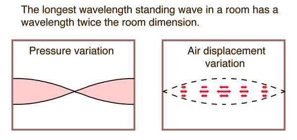
Resonators can be viewed as being made of millions of coupled moving parts (such as atoms). Therefore they can have millions of resonant frequencies, although only a few may be used in practical resonators. The vibrations inside them travel as waves, at an approximately constant velocity, bouncing back and forth between the sides of the resonator. The oppositely moving waves interfere with each other to create a pattern of standing waves in the resonator. If the distance between the sides is d\, , the length of a round trip is 2d\,. In order to cause resonance, the phase of a sinusoidal wave after a round trip has to be equal to the initial phase, so the waves will reinforce. So the condition for resonance in a resonator is that the round trip distance,2d\,, be equal to an integral number of wavelengths \lambda\, of the wave:
 
2d = N\lambda,\qquad\qquad N \in \{1,2,3...\}

If the velocity of a wave is , the frequency is  so the resonance frequencies are:
 
f = \frac{Nc}{2d}\qquad\qquad N \in \{1,2,3...\}

So the resonant frequencies of resonators, called normal modes, are equally spaced multiples (harmonics), of a lowest frequency called the fundamental frequency. The above analysis assumes the medium inside the resonator is homogeneous, so the waves travel at a constant speed, and that the shape of the resonator is rectilinear. If the resonator is inhomogeneous or has a nonrectilinear shape, like a circular drumhead or a cylindrical microwave cavity, the resonant frequencies may not occur at equally spaced multiples of the fundamental frequency. They are then called overtones instead of harmonics. There may be several such series of resonant frequencies in a single resonator, corresponding to different modes of vibration.
 
Electromagnetic
 
An electrical circuit composed of discrete components can act as a resonator when both an inductor and capacitor are included. Oscillations are limited by the inclusion of a resistor, which will be present, even if not specifically included, due to the resistance of the inductor windings. Such resonant circuits are also called RLC circuits after the circuit symbols for the components.
A distributed-parameter resonator has capacitance, inductance, and resistance that cannot be isolated into separate lumped capacitors, inductors, or resistors. An example of this, much used in filtering, is the helical resonator.
A single layer coil (or solenoid) that is used as a secondary or tertiary winding in a Tesla coil or magnifying transmitter is also a distributed resonator.
 
 
Cavity resonators
A cavity resonator is a hollow conductor blocked at both ends and along which an electromagnetic wave can be supported. It can be viewed as a waveguide short-circuited at both ends (see Microwave cavity).
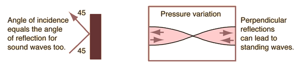
The cavity has interior surfaces which reflect a wave of a specific frequency. When a wave that is resonant with the cavity enters, it bounces back and forth within the cavity, with low loss (see standing wave). As more wave energy enters the cavity, it combines with and reinforces the standing wave, increasing its intensity.
 
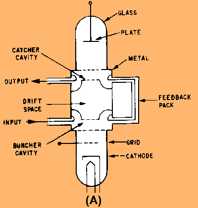
Examples
 
The cavity magnetron is a vacuum tube with a filament in the center of an evacuated, lobed, circular cavity resonator. A perpendicular magnetic field is imposed by a permanent magnet. The magnetic field causes the electrons, attracted to the (relatively) positive outer part of the chamber, to spiral outward in a circular path rather than moving directly to this anode. Spaced about the rim of the chamber are cylindrical cavities. The cavities are open along their length and so connect the common cavity space. As electrons sweep past these openings they induce a resonant high frequency radio field in the cavity, which in turn causes the electrons to bunch into groups. A portion of this field is extracted with a short antenna that is connected to a waveguide (a metal tube usually of rectangular cross section). The waveguide directs the extracted RF energy to the load, which may be a cooking chamber in a microwave oven or a high gain antenna in the case of radar.
 
RF cavities in the linac of the Australian Synchrotron are used to accelerate and bunch beams of electrons; the linac is the tube passing through the middle of the cavity
 
The klystron, tube waveguide, is a beam tube including at least two apertured cavity resonators. The beam of charged particles passes through the apertures of the resonators, often tunable wave reflection grids, in succession. A collector electrode is provided to intercept the beam after passing through the resonators. The first resonator causes bunching of the particles passing through it. The bunched particles travel in a field-free region where further bunching occurs, then the bunched particles enter the second resonator giving up their energy to excite it into oscillations. It is a particle accelerator that works in conjunction with a specifically tuned cavity by the configuration of the structures. On the beamline of an accelerator system, there are specific sections that are cavity resonators for RF.
 
An illustration of the electric and magnetic field of one of the possible modes in a cavity resonator
 
The reflex klystron is a klystron utilizing only a single apertured cavity resonator through which the beam of charged particles passes, first in one direction. A repeller electrode is provided to repel (or redirect) the beam after passage through the resonator back through the resonator in the other direction and in proper phase to reinforce the oscillations set up in the resonator.
 
In a laser, light is amplified in a cavity resonator which is usually composed of two or more mirrors. Thus an optical cavity, also known as a resonator, is a cavity with walls which reflect electromagnetic waves (light).
This will allow standing wave modes to exist with little loss outside the cavity.
 
Analogue television broadcasting 
 
Mechanical

Mechanical resonators are used in electronic circuits to generate signals of a precise frequency. These are called piezoelectric resonators, the most common of which is the quartz crystal. They are made of a thin plate of quartz with metal plates attached to each side, or in low frequency clock applications a tuning fork shape. The quartz material performs two functions. Its high dimensional stability and low temperature coefficient makes it a good resonator, keeping the resonant frequency constant. Second, the quartz's piezoelectric property converts the mechanical vibrations into an oscillating voltage, which is picked up by the plates on its surface, which are electrically attached to the circuit. These crystal oscillators are used in quartz clocks and watches, to create the clock signal that runs computers, and to stabilize the output signal from radio transmitters. Mechanical resonators can also be used to induce a standing wave in other medium. For example a multiple degree of freedom system can be created by imposing a base excitation on a cantilever beam. In this case the standing wave is imposed on the beam [1]. This type of system can be used as a sensor to track changes in frequency or phase of the resonance of the fiber. One application is as a measurement device for dimensional metrology[2].
 
Acoustic

The most familiar examples of acoustic resonators are in musical instruments. Every musical instrument has resonators. Some generate the sound directly, such as the wooden bars in a xylophone, the head of a drum, the strings in stringed instruments, and the pipes in an organ. Some modify the sound by enhancing particular frequencies, such as the sound box of a guitar or violin. Organ pipes, the bodies of woodwinds, and the sound boxes of stringed instruments are examples of acoustic cavity resonators.
 
Automobiles

The exhaust pipes in automobile exhaust systems are designed as acoustic resonators that work with the muffler to reduce noise, by making sound waves "cancel each other out"[1]. The "exhaust note" is an important feature for many vehicle owners, so both the original manufacturers and the after-market suppliers use the resonator to enhance the sound. In 'tuned exhaust' systems designed for performance the resonance of the exhaust pipes is also used to 'pull' the combustion products out of the combustion chamber quicker.
 
Percussion instruments

In many keyboard percussion instruments, below the centre of each note is a tube, which is an acoustic cavity resonator, referred to simply as the resonator. The length of the tube varies according to the pitch of the note, with higher notes having shorter resonators. The tube is open at the top end and closed at the bottom end, creating a column of air which resonates when the note is struck. This adds depth and volume to the note. In string instruments, the body of the instrument is a resonator.
The tremolo effect of a vibraphone is obtained by a mechanism which opens and shuts the resonators.
 
Stringed instruments

String instruments such as the bluegrass banjo may also have resonators. Many five-string banjos have removable resonators, to allow the instrument to be used with resonator in bluegrass style, or without in folk music style. The term resonator, used by itself, may also refer to the resonator guitar.
The modern ten-string guitar, invented by Narciso Yepes, adds four string resonators to the traditional classical guitar. By tuning these resonators in a very specific way (C, Bb, Ab, Gb) and making use of their strongest partials (corresponding to the octaves and fifths of the strings' fundamental tones), the bass strings of the guitar now resonate equally with any of the 12 tones of the chromatic octave. The Guitar Resonator is a device for driving guitar string harmonics by an electromagnetic field. This resonance effect is caused by a feedback loop and is applied to drive the fundamental tones, octaves, 5th, 3th to an infinite sustain.
 
Romero Mora Loren A. C.I:18762881
Tomado de: http://en.wikipedia.org/wiki/Resonator
CRF


Solid state (electronics)

Solid state (electronics)

Solid-state electronics are those circuits or devices built entirely from solid materials and in which the electrons, or other charge carriers, are confined entirely within the solid material. The term is often used to contrast with the earlier technologies of vacuum and gas-discharge tube devices and it is also conventional to exclude electro-mechanical devices (relays, switches and other devices with moving parts) from the term solid state.


While solid-state can include crystalline, polycrystalline and amorphous solids and refer to electrical conductors, insulators and semiconductors, the building material is most often crystalline semiconductor. Common solid-state devices include transistors, microprocessor chips, and DRAM. A considerable amount of electromagnetic and quantum-mechanical action takes place within the device. The expression became prevalent in the 1950s and the 1960s, during the transition from vacuum tube technology to semiconductor diodes and transistors. More recently, the integrated circuit (IC), the light-emitting diode (LED), and the liquid-crystal display (LCD) have evolved as further examples of solid-state devices.

In a solid-state component, the current is confined to solid elements and compounds engineered specifically to switch and amplify it. Current flow can be understood in two forms: as negatively-charged electrons, and as positively-charged electron deficiencies called electron holes or just "holes". In some semiconductors, the current consists mostly of electrons; in other semiconductors, it consists mostly of "holes". Both the electron and the hole are called charge carriers.

For data storage, solid-state devices are much faster and more reliable but are usually more expensive. Although solid-state costs continually drop, disks, tapes, and optical disks also continue to improve their cost/performance ratio.
The first solid-state device was the "cat's whisker" detector, first used in 1930s radio receivers. A whisker-like wire was moved around on a solid crystal (such as a germanium crystal) in order to detect a radio signal. The solid-state device came into its own with the invention of the transistor in 1947.


Romero Mora Loren A. C.I: 18762881
Tomado de: http://static.howstuffworks.com/gif/solid-state1.jpg
CRF


Microwave tubes

Microwave tubes

For extremely high-frequency applications (above 1 GHz), the interelectrode capacitances and transit-time delays of standard electron tube construction become prohibitive. However, there seems to be no end to the creative ways in which tubes may be constructed, and several high-frequency electron tube designs have been made to overcome these challenges.
It was discovered in 1939 that a toroidal cavity made of conductive material called a cavity resonator surrounding an electron beam of oscillating intensity could extract power from the beam without actually intercepting the beam itself. The oscillating electric and magnetic fields associated with the beam "echoed" inside the cavity, in a manner similar to the sounds of traveling automobiles echoing in a roadside canyon, allowing radio-frequency energy to be transferred from the beam to a waveguide or coaxial cable connected to the resonator with a coupling loop. The tube was called an inductive output tube, or IOT:


Two of the researchers instrumental in the initial development of the IOT, a pair of brothers named Sigurd and Russell Varian, added a second cavity resonator for signal input to the inductive output tube. This input resonator acted as a pair of inductive grids to alternately "bunch" and release packets of electrons down the drift space of the tube, so the electron beam would be composed of electrons traveling at different velocities. This "velocity modulation" of the beam translated into the same sort of amplitude variation at the output resonator, where energy was extracted from the beam. The Varian brothers called their invention a klystron.


Another invention of the Varian brothers was the reflex klystron tube. In this tube, electrons emitted from the heated cathode travel through the cavity grids toward the repeller plate, then are repelled and returned back the way they came (hence the name reflex) through the cavity grids. Self-sustaining oscillations would develop in this tube, the frequency of which could be changed by adjusting the repeller voltage. Hence, this tube operated as a voltage-controlled oscillator.


As a voltage-controlled oscillator, reflex klystron tubes served commonly as "local oscillators" for radar equipment and microwave receivers:


Initially developed as low-power devices whose output required further amplification for radio transmitter use, reflex klystron design was refined to the point where the tubes could serve as power devices in their own right. Reflex klystrons have since been superseded by semiconductor devices in the application of local oscillators, but amplification klystrons continue to find use in high-power, high-frequency radio transmitters and in scientific research applications.
One microwave tube performs its task so well and so cost-effectively that it continues to reign supreme in the competitive realm of consumer electronics: the magnetron tube. This device forms the heart of every microwave oven, generating several hundred watts of microwave RF energy used to heat food and beverages, and doing so under the most grueling conditions for a tube: powered on and off at random times and for random durations.
Magnetron tubes are representative of an entirely different kind of tube than the IOT and klystron. Whereas the latter tubes use a linear electron beam, the magnetron directs its electron beam in a circular pattern by means of a strong magnetic field:


Once again, cavity resonators are used as microwave-frequency "tank circuits," extracting energy from the passing electron beam inductively. Like all microwave-frequency devices using a cavity resonator, at least one of the resonator cavities is tapped with a coupling loop: a loop of wire magnetically coupling the coaxial cable to the resonant structure of the cavity, allowing RF power to be directed out of the tube to a load. In the case of the microwave oven, the output power is directed through a waveguide to the food or drink to be heated, the water molecules within acting as tiny load resistors, dissipating the electrical energy in the form of heat.
The magnet required for magnetron operation is not shown in the diagram. Magnetic flux runs perpendicular to the plane of the circular electron path. In other words, from the view of the tube shown in the diagram, you are looking straight at one of the magnetic poles.

Romero Mora Loren A. C.I:18762881
Tomado de: http://www.allaboutcircuits.com/vol_3/chpt_13/11.html
CRF


MICROWAVE TUBES

MICROWAVE TUBES
 
Microwave tubes perform the same functions of generation and amplification in the microwave portion of the frequency spectrum that vacuum tubes perform at lower frequencies. This section will explain the basic operation of the most widely used microwave tubes, including klystrons, traveling-wave tubes, backward-wave oscillators, magnetrons, and crossed-field amplifiers. The variations of these tubes for use in specific applications are so numerous that all of them cannot be discussed in this module. However, general principles of operation are similar in all of the variations so the explanations will be restricted to the general principles of operation.
 
The Basic Two-Cavity Klystron
 
Klystrons are velocity-modulated tubes that are used in radar and communications equipment as oscillators and amplifiers. Klystrons make use of the transit-time effect by varying the velocity of an electron beam in much the same manner as the previously discussed velocity-modulation process. Strong electrostatic fields are necessary in the klystron for efficient operation. This is necessary because the interaction of the signal and the electron beam takes place in a very short distance.
 
The construction and essential components of a TWO-CAVITY KLYSTRON are shown in view (A) of figure 2-7. View (B) is a schematic representation of the same tube. When the tube is energized, the cathode emits electrons which are focused into a beam by a low positive voltage on the control grid. The beam is then accelerated by a very high positive dc potential that is applied in equal amplitude to both the accelerator grid and the buncher grids. The buncher grids are connected to a cavity resonator that superimposes an ac potential on the dc voltage. Ac potentials are produced by oscillations within the cavity that begin spontaneously when the tube is energized. The initial oscillations are caused by random fields and circuit imbalances that are present when the circuit is energized. The oscillations within the cavity produce an oscillating electrostatic field between the buncher grids that is at the same frequency as the natural frequency of the cavity. The direction of the field changes with the frequency of the cavity. These changes alternately accelerate and decelerate the electrons of the beam passing through the grids. The area beyond the buncher grids is called the DRIFT SPACE. The electrons form bunches in this area when the accelerated electrons overtake the decelerated electrons.


Functional and schematic diagram of a two-cavity klystron.
 
Romero Mora Loren A. C.I:18762881
Tomado De: http://www.tpub.com/neets/book11/45b.htm
CRF


Microwave Tubes

Microwave Tubes

Microwave tubes are lamps that produce microwaves. Microwave tubes are electron guns for generating linear beam tubes. A microwave tube generates and amplifies higher frequencies in the microwave range of frequency spectrum. When a microwave tube is energized, the electrons are emitted from the cathode and are focused on the control grid. The emitted electrons are focused by a low positive voltage. To accelerate the electron beam, a very high positive DC voltage in equal amplitude is applied at the accelerator and buncher grid. The buncher grids superimpose AC voltage on DC voltage, which generates an electrostatic field between the buncher grids. The direction of the generated electrostatic field is governed by the frequency present in the microwave tube cavity. The continuous change in an electrostatic field accelerates and deaccelerates the electron beam. There are many types of microwave tubes. Examples include Klystrons, two-cavity Klystron, and crossed-field amplifiers. Two-cavity Klystron or Klystrons are velocity-modulated tubes. Two-cavity Klystrons are widely used as communication equipment and radar. Klystrons require a strong electrostatic field for efficient emission of an electron beam. Crossed-field amplifiers are vacuum electron devices and are generally used in master oscillator power amplifiers. Other microwave tubes are commonly available.

There are several ways in which microwave tubes function. A microwave tube works on the principle of velocity modulation. A velocity modulation principle generally avoids the problem of frequency limitation that often occurs in microwave tubes. The size of microwave tubes should range from 0.25 mm to 200 mm. An electron beam generated by a microwave source works well in the operating temperatures ranging from 910 to 1200 °C. Microwave sources are made up of materials such as tungsten, nickel, rhenium, and stainless steel. Osmium Ruthenium coating should be present on a microwave source tube. In addition, microwave sources should also have a machined tolerance of +/- 0.005mm. Microwave tubes are designed and manufactured to meet most industry standards.

Microwave tubes are used in many applications. Examples include coil formation in helical resonators and supporting resistors in high power combiners. In addition, Microwave tubes are also used in transistors and diode bases, high frequency resistor cores, conduction power tubes, and as a substrate in hybrid microelectronics. Microwave tubes should adhere to Institute of Electrical and Electronics Engineers (IEEE) 802.16 specification standards.

Romero Mora Loren C.I:18762881
Tomado de: http://www.globalspec.com/LearnMore/Optics_Optical_Components/Light_Sources/Microwave_Tubes
CRF

domingo, 18 de julio de 2010

Banda de Onda Corta

La Onda Corta, también conocida como SW (del inglés shortwave) o HF (high frequency) es una banda de radiofrecuencias comprendidas entre los 2300 y los 29999 kHz en la que transmiten (entre otras) las emisoras de radio internacionales para transmitir su programación al mundo y las estaciones de radioaficionados.

En estas frecuencias las ondas electromagnéticas, que se propagan en línea recta, rebotan a distintas alturas (cuanto más alta la frecuencia a mayor altura) de la ionosfera (con variaciones según la estación del año y la hora del día), lo que permite que las señales alcancen puntos lejanos e incluso den la vuelta al Planeta.

Se distinguen: entre 14 y 30 MHz las bandas altas o bandas diurnas cuya propagación aumenta en los días de verano, y entre 3 y 10 MHz las bandas bajas o nocturnas cuya propagación es mejor en invierno. La bandas intermedias como la de radioaficionados de 10 MHz (30m) y la de radiodifusión internacional de 25m presentan características comunes a ambas.

Las bandas nocturnas son bandas cuya propagación es mejor durante la noche, y mejor en las noches de invierno.

Las bandas diurnas son bandas que, debido a la física de la ionósfera, tienen una mejor propagación de día que de noche, y mucho mejor durante los días de verano. Además, las bandas altas presentan otros modos de propagación, comunes con los de la VHF, como las Esporádicas-E.

La estación del año influye no sólo en la duración respectiva del día y de la noche. También influye en la llamada propagación en zona gris, que permite aprovechar una buena propagación durante algunos minutos entre zonas que comparten la misma hora solar de amanecer o puesta del sol.

En radiodifusión hay las Bandas Tropicales de 90, 75 y 60 metros, y las Bandas Internacionales de 49, 41, 31, 25, 21, 19, 16, 13 y 11 metros.

Los radioaficionados cuentan con varias bandas en HF: las de 3, 7, 10, 14, 18, 21, 24 y 28 MHz, que corresponden a las bandas de 80, 40, 30, 20, 17, 15, 12 y 10 metros respectivamente.

La radio de onda corta es similar a las estaciones de onda media local (AM) que usted puede oír normalmente, sólo que la señal de onda corta viaja más distancia.

Normalmente se utiliza el modo AM (Amplitud Modulada) y la BLU o SSB (Banda Lateral Única o Single Side Band) tanto superior como inferior. También se usa el modo de telegrafía CW, el RTTY, la Frecuencia Modulada, la SSTV, entre otros tipos de modulación.

A pesar de lo que se piensa, no se necesita un super radio para oír estas transmisiones provenientes de todo el mundo. Todo lo que se necesita es una radio "normal" que pueda recibir la banda de onda corta. Tales radios pueden ser muy baratos. Para oír transmisiones Internacionales, puede usar simplemente la antena telescópica que se encuentra en muchas radios de FM. Sin embargo para la recepción de transmisiones internacionales más exóticas se debe conectar un trozo de cable ó alambre simple a la antena de su radio. Puede encontrarse mucha información al respecto en algunos programas en onda corta, en revistas como "ShortWave Magazine (SWM)", o a menudo en los grupos de noticias especializados, como "rec.radio.shortwave."

Marlon Guerrero
Electronica del Estado Solido Seccion 1

Tecnologias Celulares

.- Tecnologia CDMA
La multiplexación por división de código, acceso múltiple por división de código o CDMA (del inglés Code Division Multiple Access) es un término genérico para varios métodos de multiplexación o control de acceso al medio basados en la tecnología de espectro expandido.
CDMA emplea una tecnología de espectro expandido y un esquema especial de codificación, por el que a cada transmisor se le asigna un código único, escogido de forma que sea ortogonal respecto al del resto; el receptor capta las señales emitidas por todos los transmisores al mismo tiempo, pero gracias al esquema de codificación (que emplea códigos ortogonales entre sí) puede seleccionar la señal de interés si conoce el código empleado.
En CDMA, la señal se emite con un ancho de banda mucho mayor que el precisado por los datos a transmitir; por este motivo, la división por código es una técnica de acceso múltiple de espectro expandido. A los datos a transmitir simplemente se les aplica la función lógica XOR con el código de transmisión, que es único para ese usuario y se emite con un ancho de banda significativamente mayor que los datos.
Cada usuario de un sistema CDMA emplea un código de transmisión distinto (y único) para modular su señal. La selección del código a emplear para la modulación es vital para el buen desempeño de los sistemas CDMA, porque de él depende la selección de la señal de interés, que se hace por correlación cruzada de la señal captada con el código del usuario de interés, así como el rechazo del resto de señales y de las interferencias multi-path (producidas por los distintos rebotes de señal).


.- Tecnologia GSM
El Sistema Global para las Comunicaciones Móviles (GSM, proviene de "Groupe Special Mobile") es un sistema estándar, completamente definido, para la comunicación mediante teléfonos móviles que incorporan tecnología digital. Por ser digital cualquier cliente de GSM puede conectarse a través de su teléfono con su computador y puede hacer, enviar y recibir mensajes por e-mail, faxes, navegar por Internet, acceso seguro a la red informática de una compañía (LAN/Intranet), así como utilizar otras funciones digitales de transmisión de datos, incluyendo el Servicio de Mensajes Cortos (SMS) o mensajes de texto.

El sistema GSM basa su división de acceso al canal en combinar los siguientes modelos de reparto del espectro disponible. El primero es determinante a la hora de especificar la arquitectura de red, mientras que el resto se resuelve con circuitería en los terminales y antenas del operador:
Empleo de celdas contiguas a distintas frecuencias para repartir mejor las frecuencias (SDMA, Space Division Multiple Access o acceso múltiple por división del espacio); reutilización de frecuencias en celdas no contiguas;
División del tiempo en emisión y recepción mediante TDMA (Time Division Multiple Access, o acceso múltiple por división del tiempo);
Separación de bandas para emisión y recepción y subdivisión en canales radioeléctricos (protocolo FDMA, Frequency Division Multiple Access o acceso múltiple por división de la frecuencia);
Variación pseudoaleatoria de la frecuencia portadora de envío de terminal a red (FHMA, Frequency Hops Multiple Access o acceso múltiple por saltos de frecuencia).

La BSS, capa inferior de la arquitectura (terminal de usuario – BS – BSC), resuelve el problema del acceso del terminal al canal. La siguiente capa (NSS) se encargará, por un lado, del enrutamiento (MSC) y por otro de la identificación del abonado, tarificación y control de acceso (HLR, VLR y demás bases de datos del operador). Este párrafo con tantas siglas se explica a continuación con más calma, pero sirve de resumen general de la arquitectura de red empleada.

Por otra parte, las comunicaciones que se establezcan viajarán a través de distintos sistemas. Para simplificar, se denomina canal de comunicaciones a una comunicación establecida entre un sistema y otro, independientemente del método que realmente se emplee para establecer la conexión. En GSM hay definidos una serie de canales lógicos para el tráfico de llamadas, datos, señalización y demás propósitos.


.- Tecnologia UMTS
Sistema Universal de Telecomunicaciones Móviles (Universal Mobile Telecommunications System - UMTS) es una de las tecnologías usadas por los móviles de tercera generación (3G, también llamado W-CDMA), sucesora de GSM, debido a que la tecnología GSM propiamente dicha no podía seguir un camino evolutivo para llegar a brindar servicios considerados de Tercera Generación.
Está siendo desarrollado por 3GPP (3rd Generation Partnership Project), un proyecto común en el que colaboran: ETSI (Europa), ARIB/TIC (Japón), ANSI T-1 (USA), TTA (Korea), CWTS (China). Para alcanzar la aceptación global, 3GPP va introduciendo UMTS por fases y versiones anuales. La primera fue en 1999, describía transiciones desde redes GSM. En el 2000, se describió transiciones desde IS-95 y TDMA. ITU es la encargada de establecer el estándar para que todas las redes 3G sean compatibles.

UMTS ofrece los siguientes servicios:
.- Facilidad de uso y bajos costes: UMTS proporcionará servicios de uso fácil y adaptable para abordar las necesidades y preferencias de los usuarios, amplia gama de terminales para realizar un fácil acceso a los distintos servicios y bajo coste de los servicios para asegurar un mercado masivo. Como el roaming internacional o la capacidad de ofrecer diferentes formas de tarificación.
.- Nuevos y mejorados servicios: Los servicios de voz mantendrán una posición dominante durante varios años. Los usuarios exigirán a UMTS servicios de voz de alta calidad junto con servicios de datos e información. Las proyecciones muestran una base de abonados de servicios multimedia en fuerte crecimiento hacia el año 2010, lo que posibilita también servicios multimedia de alta calidad en áreas carentes de estas posibilidades en la red fija, como zonas de difícil acceso. Un ejemplo de esto es la posibilidad de conectarse a Internet desde el terminal móvil o desde el ordenador conectado a un terminal móvil con UMTS.

.- Acceso rápido: La principal ventaja de UMTS sobre la segunda generación móvil (2G), es la capacidad de soportar altas velocidades de transmisión de datos de hasta 144 kbit/s sobre vehículos a gran velocidad, 384 kbit/s en espacios abiertos de extrarradios y 7.2 Mbit/s con baja movilidad (interior de edificios). Esta capacidad sumada al soporte inherente del protocolo de Internet (IP), se combinan poderosamente para prestar servicios multimedia interactivos y nuevas aplicaciones de banda ancha, tales como servicios de video telefonía y video conferencia y transmisión de audio y video en tiempo real.


UMTS usa una comunicación terrestre basada en una interfaz de radio W-CDMA, conocida como UMTS Terrestrial Radio Access (UTRA). Soporta división de tiempo duplex (TDD) y división de frecuencia duplex (FDD). Ambos modelos ofrecen ratios de información de hasta 2 Mbps.

Una red UMTS se compone de los siguientes elementos:
.- Núcleo de red (Core Network). El núcleo de red incorpora funciones de transporte y de inteligencia. Las primeras soportan el transporte de la información de tráfico y señalización, incluida la conmutación. El encaminamiento reside en las funciones de inteligencia, que comprenden prestaciones como la lógica y el control de ciertos servicios ofrecidos a través de una serie de interfaces bien definidas; también incluyen la gestión de la movilidad. A través del núcleo de red, el UMTS se conecta con otras redes de telecomunicaciones, de forma que resulte posible la comunicación no sólo entre usuarios móviles UMTS, sino también con los que se encuentran conectados a otras redes.
.- Red de acceso radio (UTRAN). Desarrollada para obtener altas velocidades de transmisión. La red de acceso radio proporciona la conexión entre los terminales móviles y el Core Network. En UMTS recibe el nombre de UTRAN (Acceso Universal Radioeléctrico Terrestre) y se compone de una serie de subsistemas de redes de radio (RNS) que son el modo de comunicación de la red UMTS. Un RNS es responsable de los recursos y de la transmisión / recepción en un conjunto de celdas y esta compuesto de un RNC y uno o varios nodos B. Los nodos B son los elementos de la red que se corresponden con las estaciones base. El Controlador de la red de radio (RNC) es responsable de todo el control de los recursos lógicos de una BTS (Estación Base Transmisora).
.- UE (User Equipment). Se compone del terminal móvil y su módulo de identidad de servicios de usuario/suscriptor (USIM) equivalente a la tarjeta SIM del teléfono móvil.

Parte también de esta estructura serían las redes de transmisión empleadas para enlazar los diferentes elementos que la integran. Como los protocolos UU y IU.

Marlon Guerrero
Electronica del Estado Solido Seccion 1