In telecommunications, standing wave ratio (SWR) is the ratio of the amplitude of a partial standing wave at an antinode (maximum) to the amplitude at an adjacent node (minimum), in an electrical transmission line.
The SWR is usually defined as a voltage ratio called the VSWR, for voltage standing wave ratio. For example, the VSWR value 1.2:1 denotes a maximum standing wave amplitude that is 1.2 times greater than the minimum standing wave value. It is also possible to define the SWR in terms of current, resulting in the ISWR, which has the same numerical value. The power standing wave ratio (PSWR) is defined as the square of the VSWR.
Relationship to the reflection coefficient
Reflections occur as a result of discontinuities, such as an imperfection in an otherwise uniform transmission line, or when a transmission line is terminated with other than its characteristic impedance. The reflection coefficient Γ is defined thus:

Γ is a complex number that describes both the magnitude and the phase shift of the reflection. The simplest cases, when the imaginary part of Γ is zero, are:
- Γ = − 1: maximum negative reflection, when the line is short-circuited,
- Γ = 0: no reflection, when the line is perfectly matched,
- Γ = + 1: maximum positive reflection, when the line is open-circuited.
ρ = | Γ |

At other points, the waves interfere destructively, and the resulting amplitude Vmin is the difference between their amplitudes:

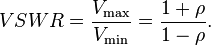
The voltage standing wave ratio is then equal to:
As ρ, the magnitude of Γ, always falls in the range [0,1], the VSWR is always ≥ +1.
The SWR can also be defined as the ratio of the maximum amplitude of the electric field strength to its minimum amplitude, i.e. Emax / Emin.
Further analysis
To understand the standing wave ratio in detail, we need to calculate the voltage (or, equivalently, the electrical field strength) at any point along the transmission line at any moment in time. We can begin with the forward wave, whose voltage as a function of time t and of distance x along the transmission line is:

where A is the amplitude of the forward wave, ω is its angular frequency and k is the wave number (equal to ω divided by the speed of the wave). The voltage of the reflected wave is a similar function, but spatially reversed (the sign of x is inverted) and attenuated by the reflection coefficient ρ:

The total voltage Vt on the transmission line is given by the superposition principle, which is just a matter of adding the two waves:

Using standard trigonometric identities, this equation can be converted to the following form:

where:

This form of the equation shows, if we ignore some of the details, that the maximum voltage over time Vmot at a distance x from the transmitter is the periodic function
This varies with x from a minimum of A(1 − ρ) to a maximum of A(1 + ρ), as we saw in the earlier, simplified discussion. A graph of Vmot against x, in the case when ρ = 0.5, is shown below. The maximum and minimum Vmot in a periods are Vmin and Vmax and are the values used to calculate the SWR.

Standing wave ratio for a range of ρ. In this graph, A and k are set to unity.
It is important to note that this graph does not show the instantaneous voltage profile along the transmission line. It only shows the maximum amplitude of the oscillation at each point. The instantaneous voltage is a function of both time and distance, so could only be shown fully by a three-dimensional or animated graph.
Practical implications of SWR
The most common case for measuring and examining SWR is when installing and tuning transmitting antennas. When a transmitter is connected to an antenna by a feed line, the impedance of the antenna and feed line must match exactly for maximum energy transfer from the feed line to the antenna to be possible. The impedance of the antenna varies based on many factors including: the antenna's natural resonance at the frequency being transmitted, the antenna's height above the ground, and the size of the conductors used to construct the antenna.
When an antenna and feedline do not have matching impedances, some of the electrical energy cannot be transferred from the feedline to the antenna. Energy not transferred to the antenna is reflected back towards the transmitter. It is the interaction of these reflected waves with forward waves which causes standing wave patterns. Reflected power has three main implications in radio transmitters: Radio Frequency (RF) energy losses increase, distortion on transmitter due to reflected power from load and damage to the transmitter can occur.
Matching the impedance of the antenna to the impedance of the feed line is typically done using an antenna tuner. The tuner can be installed between the transmitter and the feed line, or between the feed line and the antenna. Both installation methods will allow the transmitter to operate at a low SWR, however if the tuner is installed at the transmitter, the feed line between the tuner and the antenna will still operate with a high SWR, causing additional RF energy to be lost through the feedline.
Many amateur radio operators consider any impedance mismatch a serious matter.However, this is not the case. Assuming the mismatch is within the operating limits of the transmitter, the radio operator needs only be concerned with the power loss in the transmission line. Power loss will increase as the SWR increases, however the increases are often less than many radio amateurs might assume. For example, a dipole antenna tuned to operate at 3.75MHz—the center of the 80 meter amateur radio band—will exhibit an SWR of about 6:1 at the edges of the band. However, if the antenna is fed with 250 feet of RG-8A coax, the loss due to standing waves is only 2.2dB. Feed line loss typically increases with frequency, so VHF and above antennas must be matched closely to the feedline. The same 6:1 mismatch to 250 feet of RG-8A coax would incur 10.8dB of loss at 146MHz.
Romero Mora Loren C.I:18762881
Tomado de: http://en.wikipedia.org/wiki/Standing_wave_ratio
CRF
No hay comentarios:
Publicar un comentario